Minh-Ngoc Nguyen1,*
, Phuong-Lam Nguyen2
, Khac-Ky Nguyen1
, Viet-Dung Vu2
, Van-Hai Trinh3
1Department of Civil Engineering, Hanoi Architectural University, Thanh Xuan district, Hanoi, Vietnam
2 Institute of Development and Application of Sound Materials (DASM), Hoai Duc district, Hanoi, Vietnam
3 Institute of Vehicle and Energy Engineering (IVEE), Le Quy Don Technical University, Bac Tu Liem district, Hanoi, Vietnam
Abstract
In this work, we present the results of research on manufacturing composite materials based on porous glass beads for acoustic treatment. A new material with fire resistance, heat resistance, impermeability, longevity, and insulation is made from foam glass beads
(made from waste glass) and cement mortar. Firstly, the composite concrete panels with a high level of porosity 66%–82% and spherical pores in millimeter scale (i.e., ranging from 0.15mm to 10mm) are fabricated. Then, acoustical measurements are performed to characterize the sound absorbing coefficient and the transport properties of the selected composite panels.
The measurement data are compared to the semi-phenomenological Johnson-Champoux-Allard-Lafarge model to show a good agreement in terms of predicting the sound absorption property. From the obtained results it can be stated that the open porosity and the thickness of the fabricated materials affect strongly their sound absorption performance. Within a panel thickness of 33.3mm, the aerogel-based concrete panel can provide a good sound absorption coefficient which could be more than 0.60 in the frequency range of [820 1290]Hz and reach the value of 0.84 at a low resonance frequency of ~1032Hz. The methodology, therefore, enables
the identification and validation of acoustical models for specific porous glass aerogel-based materials and paves the way for an efficient exploration of the parameter space for acoustical materials design.
1 Introduction
In acoustics, porous materials are generally considered to be one of two different types of materials: rigid or resilient skeletons. In rigid-framed porous materials, the pore walls do not deform, and as a result, sound absorption occurs primarily through lossy viscous and
thermal-elastic damping when sound propagates through the pore connection system of open-air voids in the material [1, 2]
The acoustic performance of absorbing materials is governed by the mechanisms of acoustic energy dissipation during wave propagation in these media [2]. It is stated from numerous studies that the acoustical behavior (transport and absorptive properties) of absorbing layers is highly dependent on their local morphological parameters [1, 3] (porosity, pore connectivity). Thus, different approaches have been proposed to characterize the correlation between the material local geometry and the macroscopic properties [2, 4]. Recently, advances in mathematical theory, numerical computing, and signal processing have allowed a number of sophisticated methods to predict and measure the acoustical properties of porous media to be developed.
In terms of material morphology, acoustic porous media can be classified into three main types [2, 5]: foam, fibrous, and granular. Both foam and fibrous can be the best solution with the better sound absorbing coefficient as well as the potential ability to tailor sound absorption for specific ranges of frequency due to their functional advantages [6, 7].
However, some specific industrial applications require some other functional properties such as anti-flaming and high strength or damping factor, for this, we have to think about the poor absorbing metal foam or granular structures [8].
Recently, glass-bead-based materials have been studied for many different applications due to their main working functions as well as their superior properties in use such as fire resistance and environmental friendliness [7, 9, 10]. For acoustic applications, Liu et al. have studied the sound absorption performance of highly porous titanium foams with a high level of porosity of 86%–90% and spherically millimeter-scaled pores [11]. This materials provides a sound absorption ability that could be more than 0.6 in the frequency range of [3150–6300] Hz and even exceed 0.9 at the resonance frequency. In Ref. [10], the sound absorption characteristics of silica aerogel/polyester blankets are investigated by the two-microphone transfer function method. For a detailed review of porous glass aerogel-based materials for acoustic treatments, Mazrouei-Sebdan et al. introduced systematically some acoustic characterization methods and the available data on sound absorption/insulation properties of various acoustic structures based on different aerogels [9].
In the present work, we aim to introduce the methodology to fabricate and characterize the acoustical behavior (e.g., transport properties, sound absorbing coefficient) of composite panels made of porous glass aerogels.
Materials and methodology
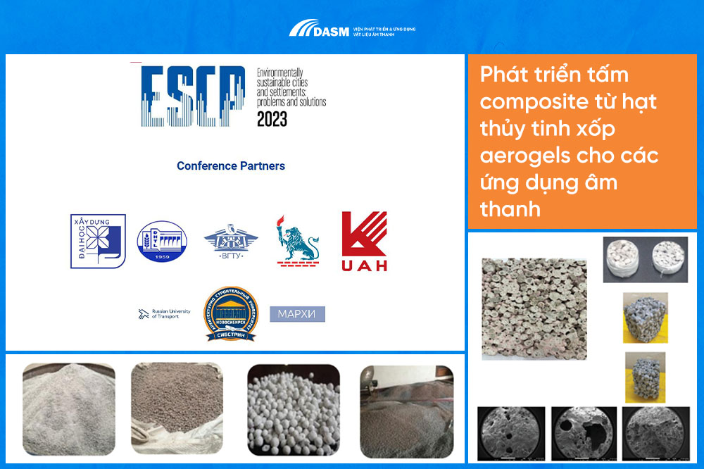
2.1 Materials: Fabrication and morphology
Fig. 1. Different size of glass beads for manufacturing the foam-based concrete
The porous aerogels/beads having tunable size and porosity are manufactured, see Fig. 1(a)-(c). In this work, the size of foam glass aerogels ranges from ~0.15mm to ~10mm within five levels as: [0.15-1.25/1.25-2.5/2.5-5.0/5.0-10]mm, see Fig. 1(d).
The foam glass aerogels then are mixed with other components and aggregates to form the concrete structures, see Fig. 2(a). In order to characterize the morphology and the
functional properties (elastic, thermal, acoustical) of the products, the testing samples are cut from the concrete panels, see Fig. 2(b)-(c). It can be noted that the size and the shape of the specimen can be different for specific tests. For example, for acoustic measurements, the specimens are required in cylindrical shape with an outer diameter of 42.4 mm (slightly smaller than the inner diameter of the impedance tube).
In Fig. 2(d)-(f), we can see the morphological features of the fabricated foam glass beads, the pore connection in the single beads shows a clear irregular distribution of shape
(mostly in spherical type) and size, this observation is obtained from the SEM imaging techniques. In addition, the boundary of the beads seems partially closed by the cement that leads to some locally closed pores in such materials.
Fig. 2. Morphology characterization of concretes based on porous glass beads
To meet the real applications, the raw concrete panels are fabricated with the final step: one/both-sided flat grinding or covered by a frame or mesh system, see Fig. 3.
Fig. 3. Ready-made construction panels for acoustic treatments and applications
2.2 Experiments
In this section, we will present the experiments used for testing the acoustic properties of the foam glass aerogels-based concrete panels (namely P1 and P2) which are fabricated by using other components and aggregates with the used factors shown in Table 1.
Table 1. Fabricated factors are controlled for fabricating ready-made concrete panels.
|
Panel Class |
Cement |
Foam glass aerogels |
Water |
Polycarboxylate superplasticizer |
Silica fume |
Volume mass |
|
|
Kg/m3 |
Kg/m3 |
Kg/m3 |
Kg/m3 |
Kg/m3 |
Kg/m3 |
|
P1 |
477.69 |
241.57 |
191.08 |
4.78 |
– |
791 |
|
P2 |
255.34 |
292.83 |
113.48 |
2.84 |
28.37 |
675 |
Fig. 4. Measurement set-up for estimation of sample open porosity
The open porosity of the concrete sample is measured by the pressure/mass method [12]. The measurement set-up is shown in Fig. 4.
The static resistivity of the composite concrete samples is obtained from the measured differential pressures 𝑝 and the controlled steady laminar 𝑝 flow rate [ 𝑄𝑄 13], according to the standard ISO 9053 [14] (method A): σ = ∆𝑝𝐴s𝐴/QLs with 𝐴𝑠 = 14. 12 𝑐𝑚2 is the cross-section area and the thickness of the sample is given as 𝐿𝑠 = 23. 9 𝑚𝑚 and 𝐿s = 33. 3 mm for the panel P1 and panel P2, respectively, see Fig. 5. The relative error of this measure is lower than 5%.
Fig. 5. Acoustic measurement of static airflow resistivity
Acoustic properties are measured with the three-microphone transfer function method [15], according to the standard ISO 10534-2 [16], see Fig. 6. The impedance tube has a total length of 1m and an inner diameter of 44.4 mm within the frequency range of [120 4300] Hz. The normal incidence sound absorption coefficient is measured through the pressure transfer function between microphones 1 and 2. Another function between microphone 2 and 3 is used for direct evaluations of the effective properties (i.e., density
and bulk modulus) and inverse estimations of the macroscopic transports (i.e., characteristic lengths, permeability, and high-frequency tortuosity) [17, 18].
Fig. 6. Impedance tube measurement: (a) detail configuration and (b) experimental set-up
2.3 Acoustic modelling
In the equivalent-fluid approach, an effective fluid is substituted for a porous medium with the effective density and effective bulk modulus given as (also referred to Johnson-Champoux-Allard-Lafarge model namely as the 5-parameter model) [1, 2]:
where ρ0 is the air density, P0 is the atmospheric pressure, γ = Cp/Cv is the ratio of heat capacities at constant pressure and volume, j is the imaginary unit, η is the dynamic viscosity. Six parameters (ϕ, Λ′, k0, α∞, Λ, and k0′ ) are the geometric and transport properties mentioned previously, see section 4.2.
Then, the wave number 𝑘 ~= ρ ~ /𝐾 ~ and the normal incidence characteristic impedance are used to describe a homogeneous layer.
Finally, the sound absorption coefficient 〈𝑆𝐴𝐶 at normal incidence of this homogeneous layer is derived as:
with the complex reflection coefficient is estimated by the following equation:
R~ = (𝑍 ~ 𝑠 − ρ0 𝑐 0 )/(𝑍 ~ 𝑠𝑠 + ρ0 𝑐0 ) in which 𝑐0𝑐 0 is the sound speed in air and is the normal incidence surface impedance of a layer with thickness Ls
3 Results and discussion
From the acoustic measurement shown in Fig. 5, the obtained static airflow resistivity and the open porosity of two samples is present in Table 2 below.
Table 2. Results of the static airflow resistivity and the open porosity of the tested samples.
Fig. 7. Experimental results of sound absorption coefficients at normal incidence of two tested concrete panels: solid lines and color zone are respectively for the mean and bounded values of two measurements for each sample.
The measured sound absorption coefficients at normal incidence of two tested concrete panels are plotted in Fig. 7. It can be stated that the sound absorption property of porous glass aerogel-based composite panels behaves like the granular medium with the quarterwavelength resonances which has a peak in the testing frequency range of [120 4300] Hz. In addition, panel P1 has a sound absorption coefficient peak of 0.97 at the frequency of ~1892Hz, while sample P2 shows a lower peak of 0.84 at the lower resonance frequency of 1032Hz.
Fig. 8. Sound absorption coefficients on one-third-octave bands.
To evaluate the sound absorption performance of two above samples, the sound absorption coefficients on one-third-octave bands from 125Hz to 4000Hz are plotted in Fig. 8 which can be used for converting the sound absorption coefficient into a single number ỏ index. The rating of sound absorption of the testing samples is defined according to ISO 11654:1997 [19] and ASTM C423-17 [20]. The rating index includes the weighted sound absorption coefficient (〈W), the noise reduction coefficient (NRC); and the sound absorption average (SAA). The obtained results show clearly that panel P2 provides the better sound absorption performance than panel P1.
Table 3. The rating of sound absorption of the testing samples
|
Single number rating |
Uni t |
P1
|
P2
|
|
αW (rating) |
|
0.15 (Not classified) |
0.35(H) (class D)
|
|
NRC
|
|
0.30
|
0.45
|
|
SAA
|
|
0.29 |
0.37 |
Next, we estimate the macroscopic transport and sound absorption properties using inverse characterization method [17, 18] with the measurement data of the three-microphone method (section 2.2) and the available values of the porosity and static airflow resistivity (shown in Table 2). The macroscopic transport properties are listed in Table 4.
Table 4. Results of macroscopic transport properties by inverse characterization method
|
Panel class |
Uni t |
P1
|
P2
|
|
Thermal characteristic length, ⊄’ |
⎧m |
3000 |
3364
|
|
Thermal characteristic length, ⊄
|
⎧m |
207 |
310
|
|
High frequency tortuosity, 〈∞ |
|
3.346 |
4929 |
|
Static thermal permeability, k0’ |
⎧m |
4.44e-8 |
132e-8 |
From the above estimations of the macroscopic properties, the computed sound absorption coefficient of the concrete samples are calculated via the semi-phenomenological model stated in section 2.3. Fig. 9 shows a good correspondence between the measured and computed sound absorption coefficient which indicates that we can use the semi-phenomenological model for designing the sound absorbers for real applications.
Fig. 9. Comparison between the measured and computed sound absorption coefficient of the porous concrete-based samples.
4 Conclusion
This present work proposed an experimental approach for fabricating and predicting the potential acoustical properties of composite panels made from porous glass aerogels. It can be concluded from the obtained results that: (i) the sound absorption property of porous glass aerogel-based composite panels behaves like the granular medium with quarter-wavelength resonances; (ii) higher value of sound absorption can be achieved in composite concrete panels with the smaller small pore connection at a low open porosity; (iii) increasing the sample thickness provides an improvement in the sound absorption coefficient and shifts the maximum sound absorption coefficient spectra towards lower frequencies
For practical applications, fabrication and testing samples with other concentrations and/or other non-acoustical properties (e.g., thermal, mechanical) will be considered in the forthcoming work.
References
1. Zieliński, T.G., et al., Benchmarks for microstructure-based modelling of sound absorbing rigid-frame porous media. Journal of Sound and Vibration, 2020. 483.
2. Allard, J. and N. Atalla, Propagation of sound in porous media: modelling sound absorbing materials 2e. 2009: John Wiley & Sons.
3. Trinh, V.H., et al., Learning acoustic responses from experiments: A multiscale-informed transfer learning approach. The Journal of the Acoustical Society of America, 2022. 151(4): p. 2587-2601.
4. Trinh, V.H., Effect of membrane content on the acoustical properties of three-dimensional monodisperse foams: Experimental, numerical and semi-analytical approaches. 2018, Ph.D. Dissertation, Paris-Est University.
5. Attenborough, K. and I.L. Vér, Sound-Absorbing Materials and Sound Absorbers. Noise and Vibration Control Engineering: Principles and Applications, 2005: p. 215-277.
6. Arenas, J.P. and M.J. Crocker, Recent trends in porous sound-absorbing materials. Sound Vib., 2010. 44(7): p. 12-18.
7. Siddika, A., A. Hajimohammadi, and V. Sahajwalla, Powder sintering and gel casting methods in making glass foam using waste glass: A review on parameters, performance, and challenges. Ceramics International, 2022. 48(2): p. 1494-1511.
8. Gasser, S., F. Paun, and Y. Bréchet, Absorptive properties of rigid porous media: Application to face centered cubic sphere packing. The Journal of the Acoustical Society of America, 2005. 117(4): p. 2090-2099.
9. Mazrouei-Sebdani, Z., et al., A review on silica aerogel-based materials for acoustic applications. Journal of Non-Crystalline Solids, 2021. 562: p. 120770. 10. Talebi, Z., et al., Silica aerogel/polyester blankets for efficient sound absorption in buildings. Construction and Building Materials, 2019. 220: p. 76-89.
11. Liu, P., H. Qing, and H. Hou, Primary investigation on sound absorption performance of highly porous titanium foams. Materials and Design, 2015. 85: p. 275-281.
12. Salissou, Y. and R. Panneton, Pressure/mass method to measure open porosity of porous solids. Journal of applied physics, 2007. 101(12): p. 124913.
13. Stinson, M.R. and G.A. Daigle, Electronic system for the measurement of flow resistance. The Journal of the Acoustical Society of America, 1988. 83(6): p. 2422-2428.
14. ISO, 9053-1:2018: Acoustics — Determination of airflow resistance — Part 1: Static airflow method. International Standards Organization: Geneva, Switzerland, 1998.
15. Salissou, Y. and R. Panneton, Wideband characterization of the complex wave number and characteristic impedance of sound absorbers. J. Acoust. Soc. Am., 2010. 128(5): p. 2868-2876.